Auto Events, Shop Projects,Car Builds, Product Reviews
Part 03 – Front Suspension Frame Splice
Side by Side
With the motor out of the Cutlass, I now had both vehicles side by side in the garage and could now get accurate measurements . I spent a day doing preliminary measurements and marking both vehicles accordingly. This takes more time than you might think. Then I contacted some friends who are accustomed at doing this kind of structural work and they will come over (at their convenience)) and add their expertise.
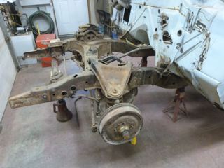
In the meantime, I spent several days cleaning the frame of the 58, up to the front quarter. The major challenge was inside the box frame of the 58. Would you believe, I got almost 3 five gallon pails of gravel, dirt etc. out. This was a frustrating job, but one that had to be done. Fortunately, the frame was still in very good condition and does not require any repairs (good old fashion steel). I took the brake booster and brake master cylinder off the Cutlass as well as the steering box and assorted components.
Professional Help
My friends from TMR, and local Draggins Car Club member Dan D, came by to take a look. Their first reaction was surprise at how similar and dimensionally close the two front ends matched were. After much looking and some thoughtful consideration, concluded that they saw no reason why they could not be swapped.
The first thing is to level both vehicles, front to back and side to side, so that you can make straight and accurate cuts. Then I commenced to check and recheck all the measurements and mark a line where the cuts will be made. You can really not take to many measurement . The two most critical lines and the first to be established is a line which will run from spindle to spindle and a line which would run front to back down the centre of the car. Once this are established in both vehicles then all other measurements can be determined. The other important aspect they then showed me was where and how the fish plates should be made. This visit was very appreciated and the expertise much valued. My confidence was starting to get stronger but was still somewhat nervous
 |
 |
 |
 |
The First Cut
Once again, TMR came through, and I was able to borrow a plasma cutter, screw jacks, jack stands and numerous other odds and sods for the project.. I did some practicing with the plasma cutter on different thicknesses of metal to get to know the machine and just what it would do. I decided that I would tackle the Cutlass first and as you can see was successful in getting the front end cut off. The plasma cutter is a great machine. It makes fast work of a difficult task. The first cut has been made and there is no turning back now.
The Second Cut
Now that I had been successful in cutting off the Cutlass front end , it was time to move on to the Chevy. With the cut line clearly marked and with plasma cutter in hand I started in. In a matter of minutes, the cuts were made and as you can see the front end was separated from the frame. Now both front ends were cut from their respective frames.
 |
 |
 |
 |
I then switched the front ends , the 78 Cutlass in front of the 58 Chevy and vise-versa.
Now, I will have to spend time cleaning this unit in preparation for the mating.
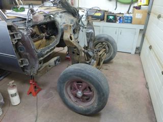
Out with the Cutlass
I lined up the now removed front end of the 58 Chevy to the frame of the Cutlass and welded them together. This was far from exact as I merely wanted to have a movable chassis and put the unit outside and move the 51 Chevy truck back into the garage.
 |
 |
Fish Plates
Once I got the 78 Cutlass front end cleaned up, I then concentrated on fabricating the fish plates that I would need to re-enforce the frame splice of the Olds front end to the Chevy. Fish plates are used on the side of a frame splice to overlap the joint and distribute the load. Again, I used the plasma cutter to cut most of then out of sheet stock and proceeded to bend them to match the contour and fit into place. This required the front end to be lined up with the frame and trial and error to fit them properly. With this task complete, I then proceeded to check all measurement and alignment in preparation for the actual welding of the new fron frame assembly onto the Chevy frame.
 |
 |
 |
Double Check
Once again, a final double check of the alignment and measurements. Is it level, is it square, is it positioned correctly?
Check, check and check again.
 |
 |
 |
 |
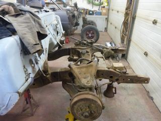
Here you get a good look at the match up of the frame sections. It shows how well the inner frame faces match up for width, and the difference in the outer frame faces.
Attachment
Finally, everything is prepared for the actual connection of the new front end and frame section from the Olds, to the 58 Chev frame. The inner faces of the frames match very closly, with 1/4 inch O.A. difference. Because of the boxing of the Olds frame, it was a question of which way to match in the frames to have the least effect on the strength, and the brackets of both the Chev body mounting points, and the Olds front end brackets for control arms etc.
With frames in position and the fish plates made and everything lined up, I started to weld the 78 Cutlass front end to the 58 Chevy frame. Now, I was able to fit the fish plates and weld accordingly.This took some time as I proceeded with care but in the end was indeed a red letter day.
 |
 |
 |
 |
With these pictures, you can start making sense of the previous statements about the fish plates and the inner and outer frame faces. The inside is virtually a perfect match up. You can now see how the outer wall of the Olds frame, has been extended straight back to ‘square out, against the front body mount bracket. Ultimately, this creates a fairly smooth transition between the frames, and hides the differences and joint nicely.
 |
 |
 |
 |
Here’s a twist you may want or NEED to consider. Some jurisdictions mandate that you MUST bolt through any frame splice, to provide a safety system if the welds were to break, the bolts and fish plates would keep things together until you get to the side of the road. While many of us look at this as rediculous and unrequired, remember one thing. Rules like this are usually created due to someones failure. Consider some of the worst welds, or worst engineering you’ve ever seen, then decide where this rule came from. Unless you are building a beautiful show chassis, this is not a bad safety net. Done right, it doesn’t create an unsightly look for a street car.
Check your local licensing or vehicle inspection to verify your local requirements.
STEERING COLUMN
The steering column shaft was a fairly straight forward connection. The 58 shaft from the steering wheel was round while the slip joint receiver for the 78 Cutlass steering box was squared off on two sides. I measured the 58 shaft to the appropriate length and cut it off. I then measured how much of the 58 shaft would go into the receiving shaft and marked. I then took the 58 shaft to the vise and using a hacksaw made a notch on the shaft (both sides to be squared). Yes, I could take the shaft to town and get it machined but I decided to give it a try. Using the spare piece that was cut off the 58 shaft I tried the following.
Using my side grinder with a 3/64 zip cut disc, I dragged it along the shaft using slight pressure and being careful. This resulted in a nice smooth surface. So, I moved ahead and proceeded to do both sides of the 58 shaft to the appropriate length. I had to keep checking my progress to the receiving shaft.
When I got real close to it going into the shaft, I switched to a file and by working both sides a little at a time was able to get it to fit very nicely into the receiver. Marking the surfaces with machinists bluing, or a felt marker pen, will provide an indicator of where your binding high points are. Of course this took some time and patience but the end result was satisfactory.
 |
 |
 |
 |
Share this:


